
ntt_accel_core multiplies two polynomials modulo
ML-KEM was published by NIST as FIPS 203 in 2024 [1], standardizing the CRYSTALS-Kyber algorithm [2]. Unlike the two elliptic curve accelerators documented elsewhere on this site, this design has nothing to do with elliptic curves. It shares a family resemblance with them anyway: a small prime field, a combinational Montgomery multiplier, and a sequencer that walks a fixed computation over a block of memory, the same shape as the point arithmetic in NIST P-256 scalar multiplication. What is genuinely new here is the transform itself.
Source: miesource/ntt-hardware-accelerator-mlkem.
Notation
| Symbol | Meaning |
|---|---|
| coefficient width, 12 bits | |
| the field modulus, 3329 | |
| polynomial degree bound, 256 | |
| a primitive 256th root of unity mod | |
| the Montgomery radix, | |
ZETAS_MONT[i] | |
GAMMAS_MONT[i] |
The field:
An element is an integer in
sum_direct  <= ('0' & a_in) + ('0' & b_in);
sum_reduced <= sum_direct - ('0' & Q_MOD);
m_out <= sum_direct(CW-1 DOWNTO 0)  WHEN sum_reduced(CW) = '1' ELSE
          sum_reduced(CW-1 DOWNTO 0);
Cost. Zero cycles. fp_mod_add and fp_mod_sub are pure combinational logic, exactly like their counterparts in the two elliptic curve designs.
Montgomery multiplication
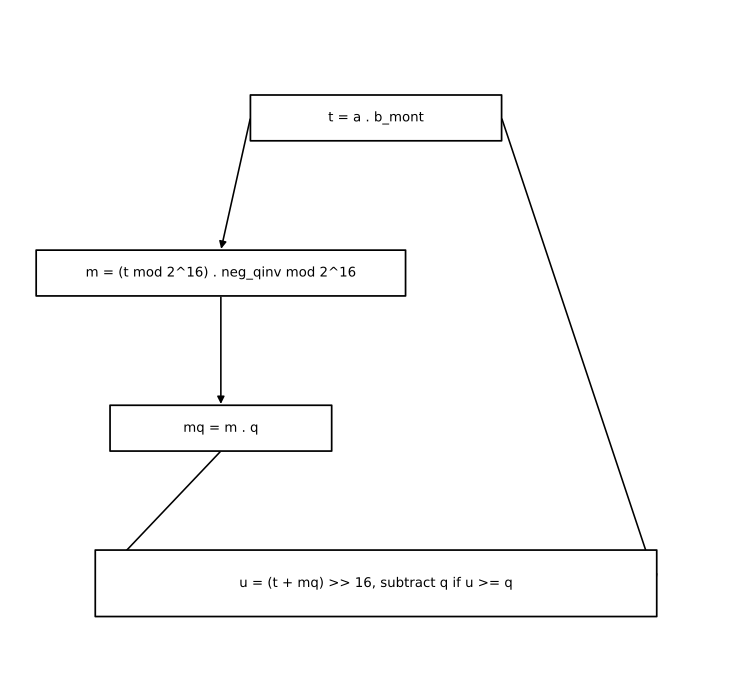
Given two values already in Montgomery form (or one plain value and one Montgomery constant), REDC recovers their product still in Montgomery form, without ever dividing by
t  ← a . b
m  ← (t mod R) . NEG_QINV mod R
mq ← m . q
u  ← (t + mq) / R
return u if u < q else u - q
t + mq is divisible by
ENTITY fp_mont_mult IS
    PORT (
        a_in : IN  UNSIGNED(CW-1 DOWNTO 0);
        b_mont_in : IN  UNSIGNED(CW-1 DOWNTO 0);
        m_out : OUT UNSIGNED(CW-1 DOWNTO 0)
    );
END ENTITY fp_mont_mult;

ARCHITECTURE dataflow OF fp_mont_mult IS
    SIGNAL t_prod   : UNSIGNED(2*CW-1 DOWNTO 0);
    SIGNAL t_low    : UNSIGNED(15 DOWNTO 0);
    SIGNAL m_prod   : UNSIGNED(15+CW DOWNTO 0);
    SIGNAL m_red    : UNSIGNED(15 DOWNTO 0);
    SIGNAL mq_prod  : UNSIGNED(15+CW DOWNTO 0);
    SIGNAL sum_full : UNSIGNED(16+CW DOWNTO 0);
    SIGNAL u_field  : UNSIGNED(CW DOWNTO 0);
    SIGNAL u_diff   : UNSIGNED(CW+1 DOWNTO 0);
BEGIN

    t_prod  <= a_in * b_mont_in;
    t_low   <= RESIZE(t_prod, 16);
    m_prod  <= t_low * NEG_QINV;
    m_red   <= RESIZE(m_prod, 16);
    mq_prod <= m_red * Q_MOD;
    sum_full <= RESIZE(t_prod, 17+CW) + RESIZE(mq_prod, 17+CW);
    u_field  <= sum_full(16+CW DOWNTO 16);
    u_diff   <= ('0' & u_field) - ("00" & Q_MOD);
    m_out <= u_field(CW-1 DOWNTO 0) WHEN u_diff(CW+1) = '1' ELSE u_diff(CW-1 DOWNTO 0);

END ARCHITECTURE dataflow;
No clk port. Every field in this entity is a SIGNAL driven by a plain assignment, not a register: the whole REDC computation is one piece of combinational logic, synthesized down to adders, a couple of small multipliers, and a comparator. Plain multiplication, needed for the base-multiplication step later, chains two of these:
ARCHITECTURE structural OF fp_mod_mult IS
    SIGNAL a_mont : UNSIGNED(CW-1 DOWNTO 0);
BEGIN

    TO_MONT : ENTITY work.fp_mont_mult
        PORT MAP (a_in => a_in, b_mont_in => R2_MOD_Q, m_out => a_mont);

    REDUCE : ENTITY work.fp_mont_mult
        PORT MAP (a_in => a_mont, b_mont_in => b_in, m_out => m_out);

END ARCHITECTURE structural;
R2_MOD_Q is
Cost. Zero cycles for either. This is a real difference from the two elliptic curve designs: their field multipliers were iterative, one bit of the multiplicand per clock cycle, because a 233-bit or 256-bit multiply is too wide to build combinationally at a reasonable clock speed. A 12-bit multiply is not. Every field multiplication in this design, however it is used downstream, costs one combinational path and no clock cycles by itself.
The butterfly
The NTT decomposes an
Inverse, Gentleman–Sande [4] form:
ARCHITECTURE structural OF ntt_butterfly_ct IS
    SIGNAL t : UNSIGNED(CW-1 DOWNTO 0);
BEGIN
    TWIDDLE : ENTITY work.fp_mont_mult
        PORT MAP (a_in => b_in, b_mont_in => zeta_mont_in, m_out => t);
    SUM : ENTITY work.fp_mod_add
        PORT MAP (a_in => a_in, b_in => t, m_out => a_out);
    DIFF : ENTITY work.fp_mod_sub
        PORT MAP (a_in => a_in, b_in => t, m_out => b_out);
END ARCHITECTURE structural;ARCHITECTURE structural OF ntt_butterfly_gs IS
SIGNAL diff_val : UNSIGNED(CW-1 DOWNTO 0);
BEGIN
SUM : ENTITY work.fp_mod_add
PORT MAP (a_in => a_in, b_in => b_in, m_out => a_out);
DIFF : ENTITY work.fp_mod_sub
PORT MAP (a_in => b_in, b_in => a_in, m_out => diff_val);
TWIDDLE : ENTITY work.fp_mont_mult
PORT MAP (a_in => diff_val, b_mont_in => zeta_mont_in, m_out => b_out);
END ARCHITECTURE structural;Cost. Zero cycles. Both butterflies are one multiplier and two adders wired together combinationally, no state of their own. A full 256-point transform needs 896 of them; ntt_core, next, is what sequences that many butterfly evaluations over a block of memory, one per clock cycle.
The transform
Both directions run in place, over the same 256-word memory, 7 layers deep. Forward NTT halves the butterfly span each layer, starting at 128:
k ← 1, length ← 128
while length >= 2:
    for start in 0, 2.length, 4.length, ... < 256:
        zeta ← ZETAS_MONT[k];  k ← k + 1
        for j in start .. start+length-1:
            t ← zeta . mem[j+length]
            mem[j+length] ← mem[j] - t
            mem[j] ← mem[j] + t
    length ← length / 2
Inverse NTT runs the layers in the opposite order, doubling the span from 2 up to 128, and finishes with a pass that multiplies every coefficient by NINV_MONT), undoing the scale factor the transform introduces:
k ← 127, length ← 2
while length <= 128:
    for start in 0, 2.length, ... < 256:
        zeta ← ZETAS_MONT[k];  k ← k - 1
        for j in start .. start+length-1:
            t ← mem[j]
            mem[j] ← mem[j] + mem[j+length]
            mem[j+length] ← zeta . (mem[j+length] - t)
    length ← length . 2
for i in 0 .. 255:
    mem[i] ← mem[i] . NINV_MONT
Every layer, forward or inverse, touches all 256 coefficients in 128 butterfly pairs, regardless of the layer's span: 7 layers times 128 pairs is 896 butterflies each direction.
PROCESS (clk, rst_n)
BEGIN
    ...
    CASE state IS
        WHEN RUN =>
            IF mode_r = '0' THEN
                mem(addr_a) <= ct_a_out;
                mem(addr_b) <= ct_b_out;
            ELSE
                mem(addr_a) <= gs_a_out;
                mem(addr_b) <= gs_b_out;
            END IF;

            IF j_r = len_r - 1 THEN
                j_r <= 0;
                IF mode_r = '0' THEN
                    k_r <= k_r + 1;
                ELSE
                    k_r <= k_r - 1;
                END IF;
                IF start_r + 2*len_r >= N_COEFFS THEN
                    start_r <= 0;
                    IF mode_r = '0' THEN
                        IF len_r = 2 THEN
                            state <= DONE_ST;
                        ELSE
                            len_r <= len_r / 2;
                        END IF;
                    ELSE
                        IF len_r = 128 THEN
                            scale_idx_r <= 0;
                            state <= SCALE_RUN;
                        ELSE
                            len_r <= len_r * 2;
                        END IF;
                    END IF;
                ELSE
                    start_r <= start_r + 2*len_r;
                END IF;
            ELSE
                j_r <= j_r + 1;
            END IF;

        WHEN SCALE_RUN =>
            mem(scale_idx_r) <= scale_out;
            IF scale_idx_r = N_COEFFS - 1 THEN
                state <= DONE_ST;
            ELSE
                scale_idx_r <= scale_idx_r + 1;
            END IF;
    ...
Both butterfly entities, CT and GS, are wired permanently to the same cur_a, cur_b, zeta_cur signals; mode_r just selects which one's outputs get written back. There is no separate datapath per direction, only a multiplexer at the write.
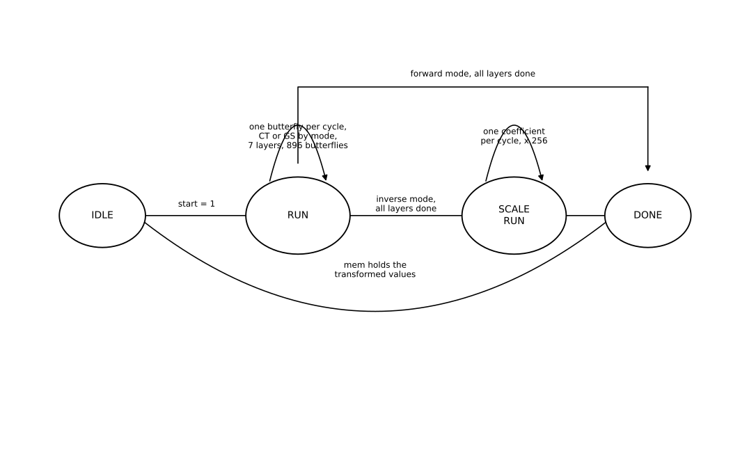
Cost. 896 cycles for a forward transform, one butterfly per cycle. 1152 for an inverse transform: the same 896 butterflies plus 256 more cycles to apply the final scaling.
Base multiplication
A pointwise product in the NTT domain is not simply pairing up coefficients:
MUL_P1 : ENTITY work.fp_mod_mult
    PORT MAP (a_in => a0_r, b_in => b0_r, m_out => p1);
MUL_T2 : ENTITY work.fp_mont_mult
    PORT MAP (a_in => a1_r, b_mont_in => gamma_cur, m_out => t2);
MUL_P2 : ENTITY work.fp_mod_mult
    PORT MAP (a_in => t2, b_in => b1_r, m_out => p2);
ADD_H0 : ENTITY work.fp_mod_add
    PORT MAP (a_in => p1, b_in => p2, m_out => h0);

MUL_P3 : ENTITY work.fp_mod_mult
    PORT MAP (a_in => a0_r, b_in => b1_r, m_out => p3);
MUL_P4 : ENTITY work.fp_mod_mult
    PORT MAP (a_in => a1_r, b_in => b0_r, m_out => p4);
ADD_H1 : ENTITY work.fp_mod_add
    PORT MAP (a_in => p3, b_in => p4, m_out => h1);
gamma_cur reads GAMMAS_MONT(i_r), already in Montgomery form, so t2 = a1 . gamma is a single Montgomery multiply; every other product here uses fp_mod_mult, since neither operand is otherwise in Montgomery form. The controller fetches one pair from each of the two transformed polynomials, computes both h0 and h1, and writes them into its own 256-word result memory:
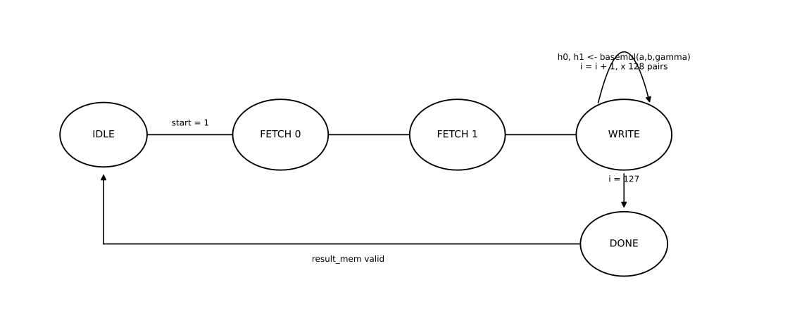
Cost. Three cycles per pair (two to fetch, one to compute and write), 128 pairs: about 384 cycles for a complete base multiplication.
Putting the three together
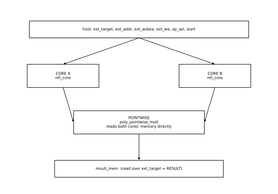
ntt_accel_core wires up two independent copies of ntt_core, called A and B, each with its own 256-word memory, plus one poly_pointwise_mult that reads directly from both cores' memories and writes its own result buffer:
CORE_A : ENTITY work.ntt_core
    PORT MAP (
        clk => clk, rst_n => rst_n, start => start_a, mode => mode_a,
        busy => busy_a, done => done_a,
        ext_addr => ext_addr, ext_wdata => ext_wdata, ext_we => ext_we_a,
        ext_rdata => ext_rdata_a,
        aux_addr => pw_a_addr, aux_rdata => pw_a_rdata
    );

POINTWISE : ENTITY work.poly_pointwise_mult
    PORT MAP (
        clk => clk, rst_n => rst_n, start => pw_start,
        busy => pw_busy, done => pw_done,
        a_addr => pw_a_addr, a_rdata => pw_a_rdata,
        b_addr => pw_b_addr, b_rdata => pw_b_rdata,
        ext_addr => ext_addr, ext_rdata => ext_rdata_pw
);aux_addr/aux_rdata is a second read port on each core's memory, separate from the host-facing ext_addr/ext_rdata port, so poly_pointwise_mult can read both transformed polynomials without contending with whatever the host happens to be doing over AXI at the same time.
Multiplying two polynomials
Reaching real hardware: AXI-Lite
Two 12-bit coefficients pack into each 32-bit AXI word, low half and high half:
| Address | Register |
|---|---|
0x000 | control: write bit 0 to start, bits 3:1 select the operation |
0x004 | status: bit 0 busy, bit 1 done |
0x008–0x208 | polynomial A, 128 words, two coefficients each |
0x208–0x408 | polynomial B |
0x408–0x608 | result (read-only) |
IF waddr_int = ADDR_CONTROL THEN
    IF wdata_r(0) = '1' THEN
        core_start   <= '1';
        op_sel_r     <= UNSIGNED(wdata_r(3 DOWNTO 1));
        done_level_r <= '0';
    END IF;
    axi_state <= WRITE_RESP;
op_sel selects one of five operations: NTT or inverse NTT on slot A, the same on slot B, or base multiplication. The write and read paths both spend one extra cycle (WRITE_ACT2 / READ_ACT2) packing or unpacking the second coefficient of each 32-bit word.
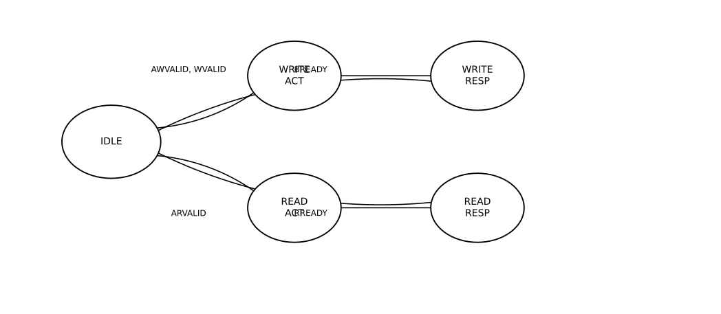
Cost. One AXI burst to load each polynomial (128 word writes), one accelerator operation, and however many status reads the host polls with.
Cost summary
| Operation | Cycles | Notes |
|---|---|---|
| Modular add / sub | 0 | combinational |
| Montgomery multiply | 0 | combinational, R = 2^16 |
| Plain multiply | 0 | two chained Montgomery multiplies, still combinational |
| CT / GS butterfly | 0 | one multiply, two adds, combinational |
| Forward NTT | 896 | 7 layers x 128 butterflies |
| Inverse NTT | 1152 | 896 butterflies + 256 scaling multiplies |
| Base multiplication | ≈ 384 | 128 pairs x 3 cycles |
| Full polynomial product | ≈ 3328 core cycles | NTT(A) + NTT(B) + basemul + INTT(A), plus the AXI round trip to move the base-multiplication result back into slot A |
Every number in this table comes from counting states and loop bounds in the RTL, the same method used throughout this site, not from a board measurement. The contrast with the two elliptic curve accelerators is the headline result: thousands of cycles here against hundreds of thousands there, because a 12-bit field multiplies combinationally in one step, where a 233-bit or 256-bit one cannot.
References
[1] National Institute of Standards and Technology, FIPS 203: Module-Lattice-Based Key-Encapsulation Mechanism Standard, August 2024. DOI 10.6028/NIST.FIPS.203.
[2] J. Bos, L. Ducas, E. Kiltz, T. Lepoint, V. Lyubashevsky, J.M. Schanck, P. Schwabe, G. Seiler, D. Stehlé, "CRYSTALS-Kyber: A CCA-Secure Module-Lattice-Based KEM," in 2018 IEEE European Symposium on Security and Privacy (EuroS&P), 2018, pp. 353–367.
[3] J.W. Cooley and J.W. Tukey, "An Algorithm for the Machine Calculation of Complex Fourier Series," Mathematics of Computation, 19(90), 1965, pp. 297–301.
[4] W.M. Gentleman and G. Sande, "Fast Fourier Transforms: For Fun and Profit," in AFIPS Fall Joint Computer Conference, vol. 29, 1966, pp. 563–578.
[5] P.L. Montgomery, "Modular Multiplication Without Trial Division," Mathematics of Computation, 44(170), 1985, pp. 519–521.