
ecc_hardware_accelerator_NIST-B233 computes
The field is GF(2^233). The curve is sect233r1, also called NIST B-233 [3, 4]. The coordinates are Modified López–Dahab [1]. This document builds the design bottom up: field, then field operations, then point operations, then the loop that ties them together.
Source: miesource/ecc_hardware_accelerator_NIST-B233.
Notation
| Symbol | Meaning |
|---|---|
| field width, 233 bits | |
| reduction polynomial, | |
| field elements, 233-bit words | |
| a point in projective coordinates | |
| the same point in affine coordinates: | |
| the curve's binary constant, 1 for this curve | |
| the scalar | |
| the base point |
The field: GF(2^233)
An element of GF(2^233) is a binary polynomial of degree less than 233, stored as a 233-bit word:
Addition is XOR. There is no carry, so a + b and a - b are the same operation.
Multiplication is polynomial multiplication followed by reduction, using
the standard reduction polynomial for B-233 [3]. Whenever a product's degree reaches 233 or higher, replace
Almost every operation below depends on one function: multiply by
CONSTANT REDUCTION_LOW : UNSIGNED(W-1 DOWNTO 0) :=
    (74 => '1', 0 => '1', OTHERS => '0');

FUNCTION xtimes(p : UNSIGNED(W-1 DOWNTO 0)) RETURN UNSIGNED IS
    VARIABLE shifted : UNSIGNED(W DOWNTO 0);
BEGIN
    shifted := p & '0';
    IF shifted(W) = '1' THEN
        RETURN shifted(W-1 DOWNTO 0) XOR REDUCTION_LOW;
    ELSE
        RETURN shifted(W-1 DOWNTO 0);
    END IF;
END FUNCTION;
REDUCTION_LOW is xtimes shifts left by one bit into a 234-bit register. If the bit that fell off the top is 1, it XORs in REDUCTION_LOW. This function lives in gf2m_pkg, and every module below calls it.
Multiplication
Multiply two field elements, a and b:
Read one bit of a at a time. If it is 1, add the current shifted copy of b. Shift b by one more power of x.
c ← 0
for i in 0 to 232:
    if bit i of a = 1:
        c ← c XOR b
    b ← xtimes(b)
return cENTITY gf2m_mult_serial IS
PORT (
clk : IN STD_LOGIC;
rst_n : IN STD_LOGIC;
start : IN STD_LOGIC;
a_in : IN UNSIGNED(W-1 DOWNTO 0);
b_in : IN UNSIGNED(W-1 DOWNTO 0);
busy : OUT STD_LOGIC;
done : OUT STD_LOGIC;
product : OUT UNSIGNED(W-1 DOWNTO 0)
);
END ENTITY gf2m_mult_serial;
ARCHITECTURE rtl OF gf2m_mult_serial IS
TYPE state_t IS (IDLE, RUN, DONE_ST);
SIGNAL state : state_t;
SIGNAL a_r, b_r, c_r : UNSIGNED(W-1 DOWNTO 0);
SIGNAL cnt : INTEGER RANGE 0 TO W-1;
BEGIN
PROCESS (clk, rst_n)
BEGIN
IF rst_n = '0' THEN
state <= IDLE;
a_r <= (OTHERS => '0');
b_r <= (OTHERS => '0');
c_r <= (OTHERS => '0');
cnt <= 0;
done <= '0';
product <= (OTHERS => '0');
ELSIF RISING_EDGE(clk) THEN
done <= '0';
CASE state IS
WHEN IDLE =>
IF start = '1' THEN
IF a_in(0) = '1' THEN
c_r <= b_in;
ELSE
c_r <= (OTHERS => '0');
END IF;
b_r <= xtimes(b_in);
a_r <= SHIFT_RIGHT(a_in, 1);
cnt <= 1;
state <= RUN;
END IF;
WHEN RUN =>
IF a_r(0) = '1' THEN
c_r <= c_r XOR b_r;
END IF;
IF cnt = W-1 THEN
state <= DONE_ST;
ELSE
b_r <= xtimes(b_r);
a_r <= SHIFT_RIGHT(a_r, 1);
cnt <= cnt + 1;
END IF;
WHEN DONE_ST =>
product <= c_r;
done <= '1';
state <= IDLE;
END CASE;
END IF;
END PROCESS;
busy <= '0' WHEN state = IDLE ELSE '1';
END ARCHITECTURE rtl;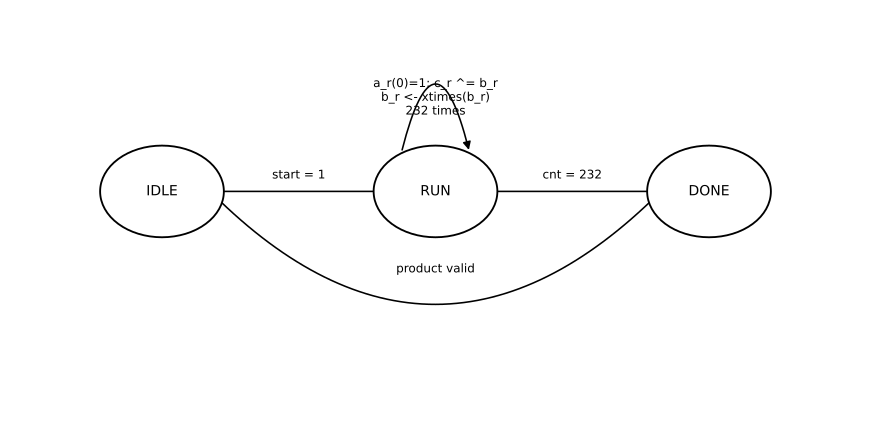
Cost. 233 cycles per call: one bit of a per cycle, one cycle to publish the result. One multiplier exists in the whole design. Every module below shares it or instantiates its own copy.
Squaring
Square a field element. In characteristic 2, squaring is linear:
The cross terms carry a factor of 2, and
for each bit i of a:
    if a_i = 1: set bit 2i of a wide (465-bit) result
reduce the wide result mod f(x), from the top bit down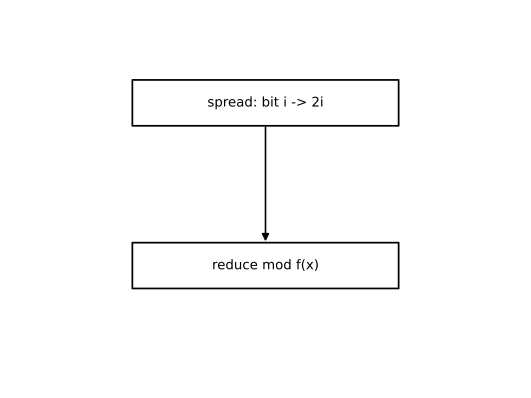
FUNCTION gf_square(a : UNSIGNED(W-1 DOWNTO 0)) RETURN UNSIGNED IS
    VARIABLE wide : UNSIGNED(2*W-2 DOWNTO 0);
BEGIN
    wide := (OTHERS => '0');
    FOR i IN 0 TO W-1 LOOP
        wide(2*i) := a(i);
    END LOOP;
    FOR i IN 2*W-2 DOWNTO W LOOP
        IF wide(i) = '1' THEN
            wide(i)      := '0';
            wide(i-W)    := wide(i-W)    XOR '1';
            wide(i-W+74) := wide(i-W+74) XOR '1';
        END IF;
    END LOOP;
    RETURN wide(W-1 DOWNTO 0);
END FUNCTION;
Bit i-W and i-W+74. Same reduction constant as xtimes, applied at an arbitrary degree.
Cost. Zero cycles. gf_square is combinational. Point doubling and inversion both call it constantly for free.
Inversion
Every nonzero element of GF(2^233) has an inverse. The multiplicative group has order
That exponent has 232 ones in it: 232 multiplications by naive repeated squaring.
The Itoh–Tsujii algorithm [2] does it in far fewer, because squaring is free here. Write
The first doubles
232 in binary is 11101000. After the leading 1, each bit is a doubling step, plus an increment step where the bit is 1:
s ← a,  k ← 1
for each bit after the leading 1 of (m-1):
    s ← frobenius(s, k) · s        # e_k → e_2k
    k ← 2k
    if bit = 1:
        s ← frobenius(s, 1) · a    # e_k → e_{k+1}
        k ← k + 1
return frobenius(s, 1)             # e_{m-1}(a)^2 = a^-1
Seven doubling steps, three increment steps: ten multiplications effectively reducing 232 to just 10.
ENTITY gf2m_inverse IS
    PORT (
        clk     : IN  STD_LOGIC;
        rst_n   : IN  STD_LOGIC;
        start   : IN  STD_LOGIC;
        a_in    : IN  UNSIGNED(W-1 DOWNTO 0);
        busy    : OUT STD_LOGIC;
        done    : OUT STD_LOGIC;
        inv_out : OUT UNSIGNED(W-1 DOWNTO 0)
    );
END ENTITY gf2m_inverse;

ARCHITECTURE rtl OF gf2m_inverse IS

    CONSTANT M_MINUS_1 : INTEGER := W - 1;
    CONSTANT NBITS      : INTEGER := 8;
    CONSTANT BITS_C : UNSIGNED(NBITS-1 DOWNTO 0) := TO_UNSIGNED(M_MINUS_1, NBITS);

    TYPE state_t IS (
        IDLE,
        DBL_FROB_START, DBL_FROB_WAIT,
        DBL_MUL_START,  DBL_MUL_WAIT,
        INCR_SQ,
        INCR_MUL_START, INCR_MUL_WAIT,
        FINAL_SQ,
        DONE_ST
    );
    SIGNAL state : state_t;

    SIGNAL a_r      : UNSIGNED(W-1 DOWNTO 0);
    SIGNAL s_r       : UNSIGNED(W-1 DOWNTO 0);
    SIGNAL s_frob_r  : UNSIGNED(W-1 DOWNTO 0);
    SIGNAL k_r       : UNSIGNED(9 DOWNTO 0);
    SIGNAL frob_cnt   : UNSIGNED(9 DOWNTO 0);
    SIGNAL bit_idx   : INTEGER RANGE 0 TO NBITS-1;

    SIGNAL m_start : STD_LOGIC;
    SIGNAL mul_a, mul_b, mul_product : UNSIGNED(W-1 DOWNTO 0);
    SIGNAL mul_busy, mul_done : STD_LOGIC;

BEGIN

    MULT : ENTITY work.gf2m_mult_serial
        PORT MAP (
            clk => clk, rst_n => rst_n,
            start => m_start, a_in => mul_a, b_in => mul_b,
            busy => mul_busy, done => mul_done, product => mul_product
        );

    PROCESS (clk, rst_n)
    BEGIN
        IF rst_n = '0' THEN
            state     <= IDLE;
            a_r       <= (OTHERS => '0');
            s_r       <= (OTHERS => '0');
            s_frob_r  <= (OTHERS => '0');
            k_r       <= (OTHERS => '0');
            frob_cnt  <= (OTHERS => '0');
            bit_idx   <= 0;
            m_start   <= '0';
            mul_a     <= (OTHERS => '0');
            mul_b     <= (OTHERS => '0');
            done      <= '0';
            inv_out   <= (OTHERS => '0');
        ELSIF RISING_EDGE(clk) THEN
            m_start <= '0';
            done    <= '0';

            CASE state IS
                WHEN IDLE =>
                    IF start = '1' THEN
                        a_r     <= a_in;
                        s_r     <= a_in;
                        k_r     <= TO_UNSIGNED(1, 10);
                        bit_idx <= NBITS - 2;
                        state   <= DBL_FROB_START;
                    END IF;

                WHEN DBL_FROB_START =>
                    s_frob_r <= s_r;
                    frob_cnt <= k_r;
                    state    <= DBL_FROB_WAIT;

                WHEN DBL_FROB_WAIT =>
                    IF frob_cnt = 0 THEN
                        mul_a   <= s_frob_r;
                        mul_b   <= s_r;
                        m_start <= '1';
                        state   <= DBL_MUL_START;
                    ELSE
                        s_frob_r <= gf_square(s_frob_r);
                        frob_cnt <= frob_cnt - 1;
                    END IF;

                WHEN DBL_MUL_START =>
                    IF mul_done = '1' THEN
                        s_r <= mul_product;
                        k_r <= SHIFT_LEFT(k_r, 1);
                        IF BITS_C(bit_idx) = '1' THEN
                            state <= INCR_SQ;
                        ELSE
                            state <= DBL_MUL_WAIT;
                        END IF;
                    END IF;

                WHEN DBL_MUL_WAIT =>
                    IF bit_idx = 0 THEN
                        state <= FINAL_SQ;
                    ELSE
                        bit_idx <= bit_idx - 1;
                        state   <= DBL_FROB_START;
                    END IF;

                WHEN INCR_SQ =>
                    mul_a   <= gf_square(s_r);
                    mul_b   <= a_r;
                    m_start <= '1';
                    state   <= INCR_MUL_START;

                WHEN INCR_MUL_START =>
                    IF mul_done = '1' THEN
                        s_r <= mul_product;
                        k_r <= k_r + 1;
                        state <= INCR_MUL_WAIT;
                    END IF;

                WHEN INCR_MUL_WAIT =>
                    IF bit_idx = 0 THEN
                        state <= FINAL_SQ;
                    ELSE
                        bit_idx <= bit_idx - 1;
                        state   <= DBL_FROB_START;
                    END IF;

                WHEN FINAL_SQ =>
                    inv_out <= gf_square(s_r);
                    state   <= DONE_ST;

                WHEN DONE_ST =>
                    done  <= '1';
                    state <= IDLE;

            END CASE;
        END IF;
    END PROCESS;

    busy <= '0' WHEN state = IDLE ELSE '1';

END ARCHITECTURE rtl;
s_r holds k_r tracks frob_cnt counts down while DBL_FROB_WAIT applies gf_square BITS_C is 232. bit_idx walks its bits below the leading one.
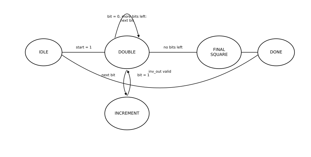
Cost. Ten multiplier calls instead of 232: roughly 10 × 233 cycles plus free squaring cycles for the Frobenius steps. Inversion is still the single most expensive operation here, but Itoh–Tsujii keeps it from dominating everything else.
Coordinates: why not affine
Affine addition divides by
López–Dahab projective coordinates [1] carry an extra coordinate
Addition and doubling use only multiplication, squaring, and addition. No division inside the loop. One inversion happens once, at the end, converting the final point back to affine.
The "modified" part removes four multiplications from addition, for the case where one point has
Point doubling
Double
S  ← square(X1)
U  ← S + Y1
T  ← mult(X1, Z1)
Z3 ← square(T)
T  ← mult(U, T)
X3 ← square(U) + T + a2·Z3
Y3 ← mult(Z3 + T, X3) + square(S)·Z3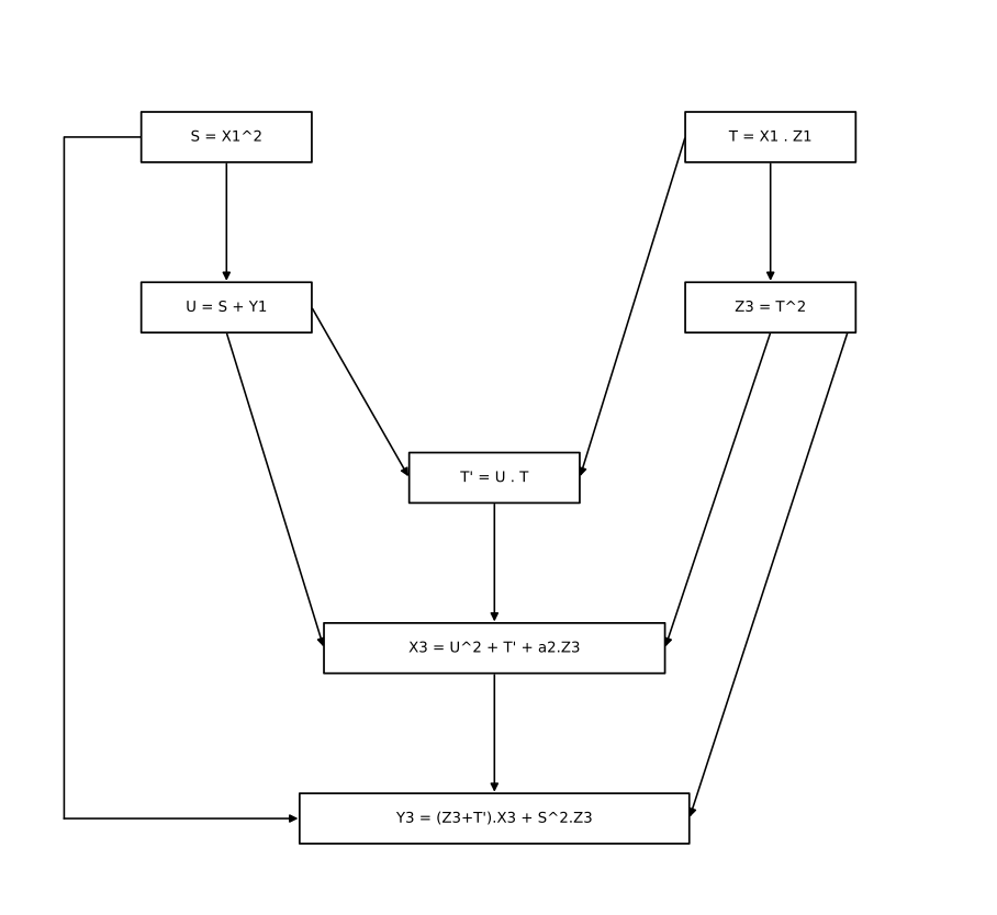
ENTITY ld_point_double IS
    PORT (
        clk    : IN  STD_LOGIC;
        rst_n  : IN  STD_LOGIC;
        start  : IN  STD_LOGIC;
        x1_in  : IN  UNSIGNED(W-1 DOWNTO 0);
        y1_in  : IN  UNSIGNED(W-1 DOWNTO 0);
        z1_in  : IN  UNSIGNED(W-1 DOWNTO 0);
        busy   : OUT STD_LOGIC;
        done   : OUT STD_LOGIC;
        x3_out : OUT UNSIGNED(W-1 DOWNTO 0);
        y3_out : OUT UNSIGNED(W-1 DOWNTO 0);
        z3_out : OUT UNSIGNED(W-1 DOWNTO 0)
    );
END ENTITY ld_point_double;

ARCHITECTURE rtl OF ld_point_double IS

    TYPE state_t IS (
        IDLE,
        ST_S_U,
        ST_MUL1_START,
        ST_Z3,
        ST_MUL2_START, ST_MUL2_WAIT,
        ST_U2_X3,
        ST_S2,
        ST_MUL3_START, ST_MUL3_WAIT,
        ST_MUL4_START, ST_MUL4_WAIT,
        ST_Y3,
        DONE_ST
    );
    SIGNAL state : state_t;

    SIGNAL x1_r, z1_r : UNSIGNED(W-1 DOWNTO 0);
    SIGNAL s_r, u_r, t_r, z3_r, u2_r, s2_r, x3_r, term1_r, y3_r : UNSIGNED(W-1 DOWNTO 0);

    SIGNAL mul_start : STD_LOGIC;
    SIGNAL mul_busy, mul_done : STD_LOGIC;
    SIGNAL mul_a, mul_b, mul_product : UNSIGNED(W-1 DOWNTO 0);

BEGIN

    MULT : ENTITY work.gf2m_mult_serial
        PORT MAP (clk, rst_n, mul_start, mul_a, mul_b, mul_busy, mul_done, mul_product);

    PROCESS (clk, rst_n)
    BEGIN
        IF rst_n = '0' THEN
            state     <= IDLE;
            mul_start <= '0';
            done      <= '0';
            x1_r <= (OTHERS => '0'); z1_r <= (OTHERS => '0');
            s_r <= (OTHERS => '0'); u_r <= (OTHERS => '0'); t_r <= (OTHERS => '0');
            z3_r <= (OTHERS => '0');
            u2_r <= (OTHERS => '0'); s2_r <= (OTHERS => '0'); x3_r <= (OTHERS => '0');
            term1_r <= (OTHERS => '0'); y3_r <= (OTHERS => '0');
            x3_out <= (OTHERS => '0'); y3_out <= (OTHERS => '0'); z3_out <= (OTHERS => '0');
        ELSIF RISING_EDGE(clk) THEN
            mul_start <= '0';
            done      <= '0';

            CASE state IS
                WHEN IDLE =>
                    IF start = '1' THEN
                        x1_r  <= x1_in;
                        z1_r  <= z1_in;
                        s_r   <= gf_square(x1_in);
                        u_r   <= gf_square(x1_in) XOR y1_in;
                        state <= ST_S_U;
                    END IF;

                WHEN ST_S_U =>
                    mul_a     <= x1_r;
                    mul_b     <= z1_r;
                    mul_start <= '1';
                    state     <= ST_MUL1_START;

                WHEN ST_MUL1_START =>
                    IF mul_done = '1' THEN
                        t_r   <= mul_product;
                        state <= ST_Z3;
                    END IF;

                WHEN ST_Z3 =>
                    z3_r  <= gf_square(t_r);
                    state <= ST_MUL2_START;

                WHEN ST_MUL2_START =>
                    mul_a     <= u_r;
                    mul_b     <= t_r;
                    mul_start <= '1';
                    state     <= ST_MUL2_WAIT;

                WHEN ST_MUL2_WAIT =>
                    IF mul_done = '1' THEN
                        t_r   <= mul_product;
                        state <= ST_U2_X3;
                    END IF;

                WHEN ST_U2_X3 =>
                    u2_r  <= gf_square(u_r);
                    x3_r  <= gf_square(u_r) XOR t_r XOR mul_a2(z3_r);
                    state <= ST_S2;

                WHEN ST_S2 =>
                    s2_r  <= gf_square(s_r);
                    state <= ST_MUL3_START;

                WHEN ST_MUL3_START =>
                    mul_a     <= z3_r XOR t_r;
                    mul_b     <= x3_r;
                    mul_start <= '1';
                    state     <= ST_MUL3_WAIT;

                WHEN ST_MUL3_WAIT =>
                    IF mul_done = '1' THEN
                        term1_r <= mul_product;
                        state   <= ST_MUL4_START;
                    END IF;

                WHEN ST_MUL4_START =>
                    mul_a     <= s2_r;
                    mul_b     <= z3_r;
                    mul_start <= '1';
                    state     <= ST_MUL4_WAIT;

                WHEN ST_MUL4_WAIT =>
                    IF mul_done = '1' THEN
                        y3_r  <= term1_r XOR mul_product;
                        state <= ST_Y3;
                    END IF;

                WHEN ST_Y3 =>
                    x3_out <= x3_r;
                    y3_out <= y3_r;
                    z3_out <= z3_r;
                    state  <= DONE_ST;

                WHEN DONE_ST =>
                    done  <= '1';
                    state <= IDLE;

            END CASE;
        END IF;
    END PROCESS;

    busy <= '0' WHEN state = IDLE ELSE '1';

END ARCHITECTURE rtl;
t_r holds two different values in sequence: first ST_Z3 before the second is written. mul_a2 applies the
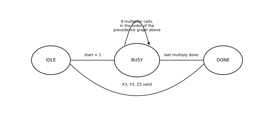
Cost. Four multiplier calls, roughly 4 × 233 cycles. No division and no restriction on
Point addition
Add a fixed point
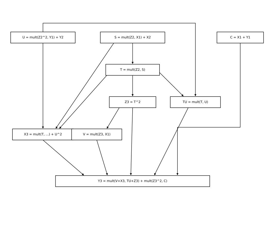
U  ← mult(square(Z2), Y1) + Y2
S  ← mult(Z2, X1) + X2
T  ← mult(Z2, S)
Z3 ← square(T)
V  ← mult(Z3, X1)
C  ← X1 + Y1
X3 ← square(U) + mult(T, U + square(S) + a2·T)
TU ← mult(T, U)
Y3 ← mult(V + X3, TU + Z3) + mult(square(Z3), C)
Eight multiplications, twice a doubling: more field elements in play and less symmetry to exploit.
ENTITY ld_point_add IS
    PORT (
        clk    : IN  STD_LOGIC;
        rst_n  : IN  STD_LOGIC;
        start  : IN  STD_LOGIC;
        x1_in  : IN  UNSIGNED(W-1 DOWNTO 0);
        y1_in  : IN  UNSIGNED(W-1 DOWNTO 0);
        x2_in  : IN  UNSIGNED(W-1 DOWNTO 0);
        y2_in  : IN  UNSIGNED(W-1 DOWNTO 0);
        z2_in  : IN  UNSIGNED(W-1 DOWNTO 0);
        busy   : OUT STD_LOGIC;
        done   : OUT STD_LOGIC;
        x3_out : OUT UNSIGNED(W-1 DOWNTO 0);
        y3_out : OUT UNSIGNED(W-1 DOWNTO 0);
        z3_out : OUT UNSIGNED(W-1 DOWNTO 0)
    );
END ENTITY ld_point_add;
No z1_in port. The formulas above require x1_in and y1_in are wired in directly, as if
ARCHITECTURE rtl OF ld_point_add IS

    TYPE state_t IS (
        IDLE,
        ST_MUL1_START,
        ST_MUL2_START,
        ST_MUL3_START, ST_MUL3_WAIT,
        ST_Z3,
        ST_MUL4_START, ST_MUL4_WAIT,
        ST_MUL5_START, ST_MUL5_WAIT,
        ST_MUL6_START,
        ST_X3,
        ST_MUL7_START, ST_MUL7_WAIT,
        ST_MUL8_START,
        ST_Y3,
        DONE_ST
    );
    SIGNAL state : state_t;

    SIGNAL x1_r, y1_r, x2_r, y2_r, z2_r : UNSIGNED(W-1 DOWNTO 0);
    SIGNAL u_r, s_r, t_r, z3_r, v_r, c_r, x3_r, tu_r, y3_r : UNSIGNED(W-1 DOWNTO 0);

    SIGNAL mul_start : STD_LOGIC;
    SIGNAL mul_busy, mul_done : STD_LOGIC;
    SIGNAL mul_a, mul_b, mul_product : UNSIGNED(W-1 DOWNTO 0);

BEGIN

    MULT : ENTITY work.gf2m_mult_serial
        PORT MAP (clk, rst_n, mul_start, mul_a, mul_b, mul_busy, mul_done, mul_product);

    PROCESS (clk, rst_n)
    BEGIN
        IF rst_n = '0' THEN
            state <= IDLE;
            mul_start <= '0';
            done <= '0';
            x1_r <= (OTHERS => '0'); y1_r <= (OTHERS => '0');
            x2_r <= (OTHERS => '0'); y2_r <= (OTHERS => '0'); z2_r <= (OTHERS => '0');
            u_r <= (OTHERS => '0'); s_r <= (OTHERS => '0'); t_r <= (OTHERS => '0');
            z3_r <= (OTHERS => '0'); v_r <= (OTHERS => '0'); c_r <= (OTHERS => '0');
            x3_r <= (OTHERS => '0'); tu_r <= (OTHERS => '0'); y3_r <= (OTHERS => '0');
            x3_out <= (OTHERS => '0'); y3_out <= (OTHERS => '0'); z3_out <= (OTHERS => '0');
        ELSIF RISING_EDGE(clk) THEN
            mul_start <= '0';
            done      <= '0';

            CASE state IS
                WHEN IDLE =>
                    IF start = '1' THEN
                        x1_r <= x1_in; y1_r <= y1_in;
                        x2_r <= x2_in; y2_r <= y2_in; z2_r <= z2_in;
                        c_r  <= x1_in XOR y1_in;
                        mul_a <= gf_square(z2_in);
                        mul_b <= y1_in;
                        mul_start <= '1';
                        state <= ST_MUL1_START;
                    END IF;

                WHEN ST_MUL1_START =>
                    IF mul_done = '1' THEN
                        u_r   <= mul_product XOR y2_r;
                        mul_a <= z2_r;
                        mul_b <= x1_r;
                        mul_start <= '1';
                        state <= ST_MUL2_START;
                    END IF;

                WHEN ST_MUL2_START =>
                    IF mul_done = '1' THEN
                        s_r   <= mul_product XOR x2_r;
                        mul_a <= z2_r;
                        state <= ST_MUL3_START;
                    END IF;

                WHEN ST_MUL3_START =>
                    mul_b     <= s_r;
                    mul_start <= '1';
                    state     <= ST_MUL3_WAIT;

                WHEN ST_MUL3_WAIT =>
                    IF mul_done = '1' THEN
                        t_r   <= mul_product;
                        state <= ST_Z3;
                    END IF;

                WHEN ST_Z3 =>
                    z3_r  <= gf_square(t_r);
                    state <= ST_MUL4_START;

                WHEN ST_MUL4_START =>
                    mul_a     <= z3_r;
                    mul_b     <= x1_r;
                    mul_start <= '1';
                    state     <= ST_MUL4_WAIT;

                WHEN ST_MUL4_WAIT =>
                    IF mul_done = '1' THEN
                        v_r   <= mul_product;
                        state <= ST_MUL5_START;
                    END IF;

                WHEN ST_MUL5_START =>
                    mul_a     <= t_r;
                    mul_b     <= u_r XOR gf_square(s_r) XOR mul_a2(t_r);
                    mul_start <= '1';
                    state     <= ST_MUL5_WAIT;

                WHEN ST_MUL5_WAIT =>
                    IF mul_done = '1' THEN
                        x3_r  <= gf_square(u_r) XOR mul_product;
                        mul_a <= t_r;
                        mul_b <= u_r;
                        mul_start <= '1';
                        state <= ST_MUL6_START;
                    END IF;

                WHEN ST_MUL6_START =>
                    IF mul_done = '1' THEN
                        tu_r  <= mul_product;
                        state <= ST_X3;
                    END IF;

                WHEN ST_X3 =>
                    state <= ST_MUL7_START;

                WHEN ST_MUL7_START =>
                    mul_a     <= v_r XOR x3_r;
                    mul_b     <= tu_r XOR z3_r;
                    mul_start <= '1';
                    state     <= ST_MUL7_WAIT;

                WHEN ST_MUL7_WAIT =>
                    IF mul_done = '1' THEN
                        y3_r  <= mul_product;
                        mul_a <= gf_square(z3_r);
                        mul_b <= c_r;
                        mul_start <= '1';
                        state <= ST_MUL8_START;
                    END IF;

                WHEN ST_MUL8_START =>
                    IF mul_done = '1' THEN
                        y3_r  <= y3_r XOR mul_product;
                        state <= ST_Y3;
                    END IF;

                WHEN ST_Y3 =>
                    x3_out <= x3_r;
                    y3_out <= y3_r;
                    z3_out <= z3_r;
                    state  <= DONE_ST;

                WHEN DONE_ST =>
                    done  <= '1';
                    state <= IDLE;

            END CASE;
        END IF;
    END PROCESS;

    busy <= '0' WHEN state = IDLE ELSE '1';

END ARCHITECTURE rtl;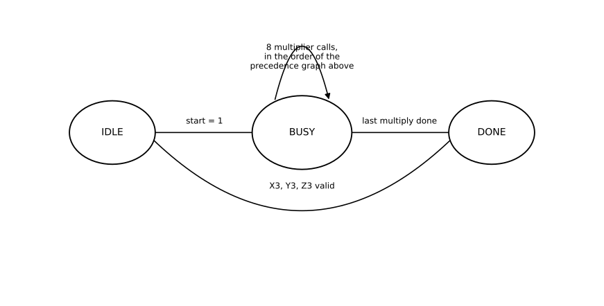
Cost. Eight multiplier calls, roughly 8 × 233 cycles. This module cannot add two points that both have
Scalar multiplication
Compute
A right-to-left walk would double the base point itself; after the first doubling it would no longer have
acc ← point at infinity
for i from (n-1) downto 0:
    acc ← double(acc)
    if bit i of k = 1:
        acc ← add(P, acc)          # P always has Z = 1
return to_affine(acc)
double on infinity, and add when the accumulator is still infinity, are not cases the formulas above handle. The VHDL treats both explicitly.
ENTITY ecc_hardware_accelerator_NIST-B233 IS
    GENERIC (
        KBITS : INTEGER := W
    );
    PORT (
        clk    : IN  STD_LOGIC;
        rst_n  : IN  STD_LOGIC;
        start  : IN  STD_LOGIC;
        k_in   : IN  UNSIGNED(KBITS-1 DOWNTO 0);
        k_len  : IN  INTEGER RANGE 0 TO KBITS;
        px_in  : IN  UNSIGNED(W-1 DOWNTO 0);
        py_in  : IN  UNSIGNED(W-1 DOWNTO 0);
        busy   : OUT STD_LOGIC;
        done   : OUT STD_LOGIC;
        result_is_infinity : OUT STD_LOGIC;
        qx_out : OUT UNSIGNED(W-1 DOWNTO 0);
        qy_out : OUT UNSIGNED(W-1 DOWNTO 0)
    );
END ENTITY ecc_hardware_accelerator_NIST-B233;
k_len = 0 is a shortcut for
ARCHITECTURE rtl OF ecc_hardware_accelerator_NIST-B233 IS
    ...
BEGIN

    PD : ENTITY work.ld_point_double
        PORT MAP (
            clk => clk, rst_n => rst_n,
            start => pd_start,
            x1_in => xacc, y1_in => yacc, z1_in => zacc,
            busy => pd_busy, done => pd_done,
            x3_out => pd_x3, y3_out => pd_y3, z3_out => pd_z3
        );

    PA : ENTITY work.ld_point_add
        PORT MAP (
            clk => clk, rst_n => rst_n,
            start => pa_start,
            x1_in => px_r, y1_in => py_r,
            x2_in => xacc, y2_in => yacc, z2_in => zacc,
            busy => pa_busy, done => pa_done,
            x3_out => pa_x3, y3_out => pa_y3, z3_out => pa_z3
        );
PD always doubles the accumulator. PA always adds the fixed base point into it. The bit loop:
                WHEN BIT_LOOP_DBL_START =>
                    pd_start <= '1';
                    state    <= BIT_LOOP_DBL_WAIT;

                WHEN BIT_LOOP_DBL_WAIT =>
                    IF pd_done = '1' THEN
                        xacc <= pd_x3;
                        yacc <= pd_y3;
                        zacc <= pd_z3;
                        IF k_r(bit_idx) = '1' THEN
                            IF pd_z3 = TO_UNSIGNED(0, W) THEN
                                xacc  <= px_r;
                                yacc  <= py_r;
                                zacc  <= TO_UNSIGNED(1, W);
                                state <= BIT_LOOP_NEXT;
                            ELSE
                                state <= BIT_LOOP_ADD_START;
                            END IF;
                        ELSE
                            state <= BIT_LOOP_NEXT;
                        END IF;
                    END IF;

                WHEN BIT_LOOP_ADD_START =>
                    pa_start <= '1';
                    state    <= BIT_LOOP_ADD_WAIT;

                WHEN BIT_LOOP_ADD_WAIT =>
                    IF pa_done = '1' THEN
                        xacc  <= pa_x3;
                        yacc  <= pa_y3;
                        zacc  <= pa_z3;
                        state <= BIT_LOOP_NEXT;
                    END IF;

                WHEN BIT_LOOP_NEXT =>
                    IF bit_idx = 0 THEN
                        state <= CONVERT_ZINV_START;
                    ELSE
                        bit_idx <= bit_idx - 1;
                        state   <= BIT_LOOP_DBL_START;
                    END IF;
The accumulator starts at pd_z3 = 0 catches the moment a bit says "add a point" but the accumulator is still infinity; the state machine loads the base point directly instead of calling ld_point_add with a
Converting back to affine uses the same relation as before. Note
                WHEN CONVERT_ZINV_START =>
                    IF zacc = TO_UNSIGNED(0, W) THEN
                        result_is_infinity <= '1';
                        state <= DONE_ST;
                    ELSE
                        inv_start <= '1';
                        state     <= CONVERT_ZINV_WAIT;
                    END IF;

                WHEN CONVERT_ZINV_WAIT =>
                    IF inv_done = '1' THEN
                        zinv_r <= inv_out;
                        state  <= CONVERT_ZINV2;
                    END IF;

                WHEN CONVERT_ZINV2 =>
                    zinv2_r   <= gf_square(zinv_r);
                    mul_a     <= xacc;
                    mul_b     <= zinv_r;
                    mul_start <= '1';
                    state     <= CONVERT_MULX_START;

                WHEN CONVERT_MULX_START =>
                    IF mul_done = '1' THEN
                        qx_out <= mul_product;
                        mul_a  <= yacc;
                        mul_b  <= zinv2_r;
                        mul_start <= '1';
                        state  <= CONVERT_MULY_START;
                    END IF;

                WHEN CONVERT_MULY_START =>
                    IF mul_done = '1' THEN
                        qy_out <= mul_product;
                        state  <= DONE_ST;
                    END IF;
zinv2_r is computed with gf_square at no extra cost, alongside starting the multiplier on xacc * zinv_r.
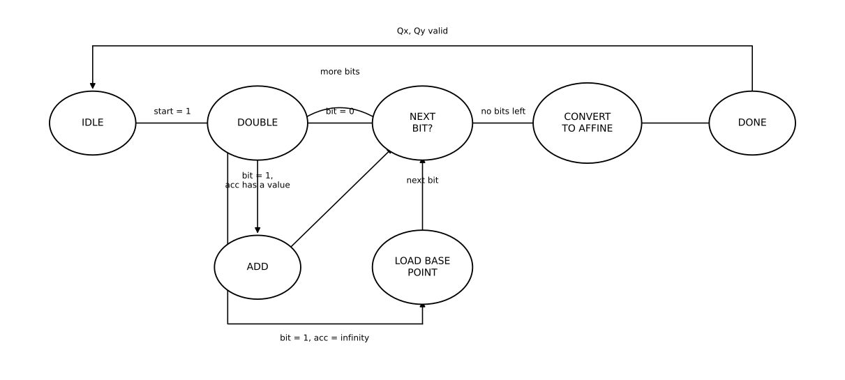
Cost. One inversion (about ten multiplier calls), two more calls for the coordinate multiplications paid once. On top of that: up to 233 doublings, and one addition for every set bit of
Reaching real hardware
Simulation checks the formulas. It does not check a bitstream on a real FPGA, over real wires. ecc_uart_top wraps the scalar multiplier in a UART protocol.
A scalar arrives as 30 bytes, big-endian. The reply is 61 bytes: one status byte, then
CONSTANT GX : UNSIGNED(W-1 DOWNTO 0) :=
    233X"0fac9dfcbac8313bb2139f1bb755fef65bc391f8b36f8f8eb7371fd558b";
CONSTANT GY : UNSIGNED(W-1 DOWNTO 0) :=
    233X"1006a08a41903350678e58528bebf8a0beff867a7ca36716f7e01f81052";

CONSTANT NBYTES   : INTEGER := (W + 7) / 8;
CONSTANT PAD_BITS : INTEGER := 8*NBYTES - W;GX, GY are sect233r1's generator [3], wired into px_in/py_in, so the host only sends k.
                WHEN LOAD_RESPONSE =>
                    IF ecc_inf = '1' THEN
                        tx_shift <= X"01" &
                                    STD_LOGIC_VECTOR(TO_UNSIGNED(0, 8*NBYTES)) &
                                    STD_LOGIC_VECTOR(TO_UNSIGNED(0, 8*NBYTES));
                    ELSE
                        tx_shift <= X"00" &
                                    STD_LOGIC_VECTOR(TO_UNSIGNED(0, PAD_BITS)) & STD_LOGIC_VECTOR(ecc_qx) &
                                    STD_LOGIC_VECTOR(TO_UNSIGNED(0, PAD_BITS)) & STD_LOGIC_VECTOR(ecc_qy);
                    END IF;
                    tx_byte_cnt <= 0;
                    state       <= TX_BYTE_START;
uart_rx and uart_tx handle ordinary 8N1 framing at 115200 baud, not shown here.
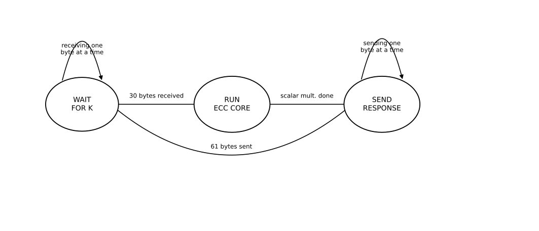
Cost. One 30-byte receive, one scalar multiplication, one 61-byte send per request.
Cost summary
| Operation | Multiplier calls | Cycles | Notes |
|---|---|---|---|
| Addition | 0 | 0 | XOR, combinational |
| Squaring | 0 | 0 | combinational |
| Multiplication | 1 | 233 | shift-and-add |
| Inversion | 10 | ≈ 10 × 233 | Itoh–Tsujii [2] |
| Point doubling | 4 | ≈ 4 × 233 | any |
| Point addition | 8 | ≈ 8 × 233 | requires |
| Scalar multiplication | ≤ 233 doublings, ≤ 233 additions, 1 inversion, 2 | varies | left-to-right double-and-add |
References
[1] J. López and R. Dahab, "Improved Algorithms for Elliptic Curve Arithmetic in GF(2^n)," in Selected Areas in Cryptography (SAC 1998), LNCS 1556, Springer, 1999, pp. 201–212.
[2] T. Itoh and S. Tsujii, "A Fast Algorithm for Computing Multiplicative Inverses in GF(2^m) Using Normal Bases," Information and Computation, vol. 78, no. 3, pp. 171–177, 1988.
[3] Standards for Efficient Cryptography Group, SEC 2: Recommended Elliptic Curve Domain Parameters, Version 1.0, 2000. (sect233r1 / NIST B-233)
[4] National Institute of Standards and Technology, FIPS PUB 186-4: Digital Signature Standard (DSS), 2013. Appendix D.