
ecc_scalar_mult and ecc_scalar_mult_ct both compute
The field is GF(p), a prime field, not a binary one. That single fact changes almost everything downstream of it: squaring is no longer free, the reduction step is subtraction instead of XOR, and the coordinate system is Jacobian rather than López–Dahab. Where the previous document, on GF(2^233) scalar multiplication, built up binary-field hardware, this one builds the prime-field equivalent, then shows what changes when a design has to run in constant time.
Source: miesource/ecc-hardware-accelerator-NIST-P256.
Notation
| Symbol | Meaning |
|---|---|
| field width, 256 bits | |
| the field modulus, a 256-bit prime | |
| field elements, 256-bit words | |
| a point in Jacobian coordinates | |
| the same point in affine coordinates: | |
| the base point | |
| the scalar |
The field: GF(p)
An element of GF(p) is an integer in
Compute the sum with one extra bit of headroom, subtract
ENTITY fp_mod_add IS
    PORT (
        a_in : IN  UNSIGNED(W-1 DOWNTO 0);
        b_in : IN  UNSIGNED(W-1 DOWNTO 0);
        m_out : OUT UNSIGNED(W-1 DOWNTO 0)
    );
END ENTITY fp_mod_add;

ARCHITECTURE dataflow OF fp_mod_add IS
    SIGNAL sum_direct : UNSIGNED(W DOWNTO 0);
    SIGNAL sum_reduced : UNSIGNED(W DOWNTO 0);
BEGIN

    sum_direct  <= ('0' & a_in) + ('0' & b_in);
    sum_reduced <= sum_direct - ('0' & P_MOD);
    m_out <= sum_direct(W-1 DOWNTO 0)  WHEN sum_reduced(W) = '1' ELSE
              sum_reduced(W-1 DOWNTO 0);

END ARCHITECTURE dataflow;
sum_reduced is the sum minus W of sum_reduced is set (still 1, meaning negative in this width), and the correction was unnecessary: the raw sum was already in range. Subtraction mirrors this, adding
ARCHITECTURE dataflow OF fp_mod_sub IS
    SIGNAL diff_direct : UNSIGNED(W DOWNTO 0);
    SIGNAL diff_plus_p : UNSIGNED(W DOWNTO 0);
BEGIN

    diff_direct <= ('0' & a_in) - ('0' & b_in);
    diff_plus_p <= diff_direct + ('0' & P_MOD);
    m_out <= diff_direct(W-1 DOWNTO 0) WHEN diff_direct(W) = '0' ELSE
              diff_plus_p(W-1 DOWNTO 0);

END ARCHITECTURE dataflow;
Cost. Zero cycles for either. Both are pure combinational logic: one adder or subtractor, one comparison, one multiplexer. Every module below uses these two constantly, for free.
Multiplication
Binary fields let squaring skip straight to bit-spreading; prime fields do not. Multiplication mod
c ← 0
for i from 255 downto 0:
    c ← 2c mod p
    if bit i of a = 1:
        c ← c + b mod p
return cENTITY fp_mult_interleaved IS
PORT (
clk : IN STD_LOGIC;
rst_n : IN STD_LOGIC;
start : IN STD_LOGIC;
a_in : IN UNSIGNED(W-1 DOWNTO 0);
b_in : IN UNSIGNED(W-1 DOWNTO 0);
busy : OUT STD_LOGIC;
done : OUT STD_LOGIC;
product : OUT UNSIGNED(W-1 DOWNTO 0)
);
END ENTITY fp_mult_interleaved;
ARCHITECTURE rtl OF fp_mult_interleaved IS
TYPE state_t IS (IDLE, RUN, DONE_ST);
SIGNAL state : state_t;
SIGNAL a_r, b_r, c_r : UNSIGNED(W-1 DOWNTO 0);
SIGNAL cnt : INTEGER RANGE 0 TO W-1;
SIGNAL c_doubled : UNSIGNED(W-1 DOWNTO 0);
SIGNAL c_plus_b : UNSIGNED(W-1 DOWNTO 0);
SIGNAL c_next : UNSIGNED(W-1 DOWNTO 0);
BEGIN
DOUBLER : ENTITY work.fp_mod_add
PORT MAP (a_in => c_r, b_in => c_r, m_out => c_doubled);
ADDER : ENTITY work.fp_mod_add
PORT MAP (a_in => c_doubled, b_in => b_r, m_out => c_plus_b);
c_next <= c_plus_b WHEN a_r(cnt) = '1' ELSE c_doubled;
PROCESS (clk, rst_n)
BEGIN
IF rst_n = '0' THEN
state <= IDLE;
a_r <= (OTHERS => '0');
b_r <= (OTHERS => '0');
c_r <= (OTHERS => '0');
cnt <= 0;
done <= '0';
product <= (OTHERS => '0');
ELSIF RISING_EDGE(clk) THEN
done <= '0';
CASE state IS
WHEN IDLE =>
IF start = '1' THEN
a_r <= a_in;
b_r <= b_in;
c_r <= (OTHERS => '0');
cnt <= W - 1;
state <= RUN;
END IF;
WHEN RUN =>
c_r <= c_next;
IF cnt = 0 THEN
state <= DONE_ST;
ELSE
cnt <= cnt - 1;
END IF;
WHEN DONE_ST =>
product <= c_r;
done <= '1';
state <= IDLE;
END CASE;
END IF;
END PROCESS;
busy <= '0' WHEN state = IDLE ELSE '1';
END ARCHITECTURE rtl;c_doubled and c_plus_b are two fp_mod_add instances wired in series, always computing both "just double" and "double, then add c_next picks between them combinationally based on the current bit of a. There is no separate reduction step afterward, because fp_mod_add already keeps every intermediate value under
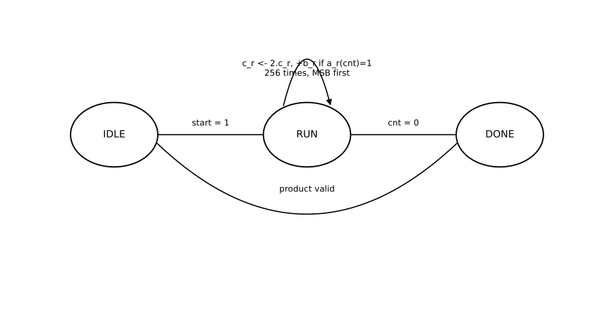
Cost. 256 cycles per call, one bit of a per cycle. One multiplier exists in this design; every module below shares it or instantiates its own copy.
Inversion
Fermat's little theorem gives the inverse directly: for prime
In GF(2^233), squaring was free, so Itoh–Tsujii could turn this into ten multiplications. Here, squaring is an ordinary call to the same multiplier as everything else. There is no shortcut: fp_inverse computes
result ← 1
for i from 255 downto 0:
    result ← result^2
    if bit i of (p-2) = 1:
        result ← result . a
return resultENTITY fp_inverse IS
PORT (
clk : IN STD_LOGIC;
rst_n : IN STD_LOGIC;
start : IN STD_LOGIC;
a_in : IN UNSIGNED(W-1 DOWNTO 0);
busy : OUT STD_LOGIC;
done : OUT STD_LOGIC;
inv_out : OUT UNSIGNED(W-1 DOWNTO 0)
);
END ENTITY fp_inverse;
ARCHITECTURE rtl OF fp_inverse IS
TYPE state_t IS (IDLE, SQ_START, SQ_WAIT, MUL_START, MUL_WAIT, NEXT_BIT, DONE_ST);
SIGNAL state : state_t;
SIGNAL a_r, result_r : UNSIGNED(W-1 DOWNTO 0);
SIGNAL bit_idx : INTEGER RANGE 0 TO W-1;
SIGNAL m_start : STD_LOGIC;
SIGNAL mul_a, mul_b, mul_product : UNSIGNED(W-1 DOWNTO 0);
SIGNAL mul_busy, mul_done : STD_LOGIC;
BEGIN
MULT : ENTITY work.fp_mult_interleaved
PORT MAP (
clk => clk, rst_n => rst_n,
start => m_start, a_in => mul_a, b_in => mul_b,
busy => mul_busy, done => mul_done, product => mul_product
);
PROCESS (clk, rst_n)
BEGIN
IF rst_n = '0' THEN
state <= IDLE;
a_r <= (OTHERS => '0');
result_r <= (OTHERS => '0');
bit_idx <= 0;
m_start <= '0';
mul_a <= (OTHERS => '0');
mul_b <= (OTHERS => '0');
done <= '0';
inv_out <= (OTHERS => '0');
ELSIF RISING_EDGE(clk) THEN
m_start <= '0';
done <= '0';
CASE state IS
WHEN IDLE =>
IF start = '1' THEN
a_r <= a_in;
result_r <= TO_UNSIGNED(1, W);
bit_idx <= W - 1;
state <= SQ_START;
END IF;
WHEN SQ_START =>
mul_a <= result_r;
mul_b <= result_r;
m_start <= '1';
state <= SQ_WAIT;
WHEN SQ_WAIT =>
IF mul_done = '1' THEN
result_r <= mul_product;
IF P_MINUS_2(bit_idx) = '1' THEN
state <= MUL_START;
ELSE
state <= NEXT_BIT;
END IF;
END IF;
WHEN MUL_START =>
mul_a <= result_r;
mul_b <= a_r;
m_start <= '1';
state <= MUL_WAIT;
WHEN MUL_WAIT =>
IF mul_done = '1' THEN
result_r <= mul_product;
state <= NEXT_BIT;
END IF;
WHEN NEXT_BIT =>
IF bit_idx = 0 THEN
state <= DONE_ST;
ELSE
bit_idx <= bit_idx - 1;
state <= SQ_START;
END IF;
WHEN DONE_ST =>
inv_out <= result_r;
done <= '1';
state <= IDLE;
END CASE;
END IF;
END PROCESS;
busy <= '0' WHEN state = IDLE ELSE '1';
END ARCHITECTURE rtl;P_MINUS_2 is
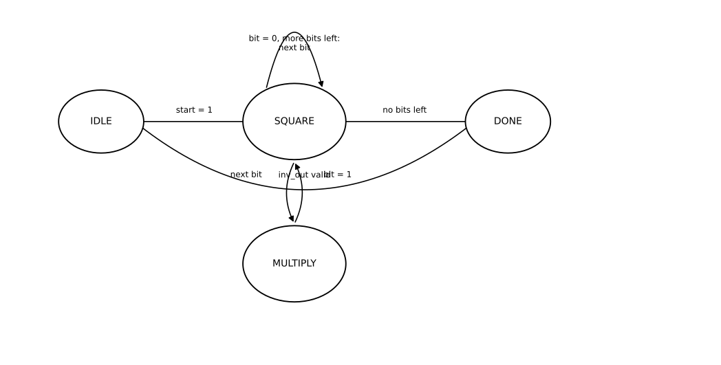
Cost. 384 multiplier calls: 256 for the squarings, 128 for the multiplications. Compare that to GF(2^233)'s ten. The whole reason Itoh–Tsujii worked there was that squaring was free; here it costs exactly as much as any other multiplication, so square-and-multiply is already close to the best available. Inversion is, by a wide margin, the most expensive single operation in this design.
Coordinates: why Jacobian
Affine addition needs a field inversion, and inversion here costs 384 multiplications. Paying that on every point operation in a 256-bit scalar multiplication loop is not an option.
Jacobian coordinates defer it the same way López–Dahab coordinates did for the binary curve, with a different relation between projective and affine coordinates:
Addition and doubling use only multiplication and addition in
Point doubling
Given
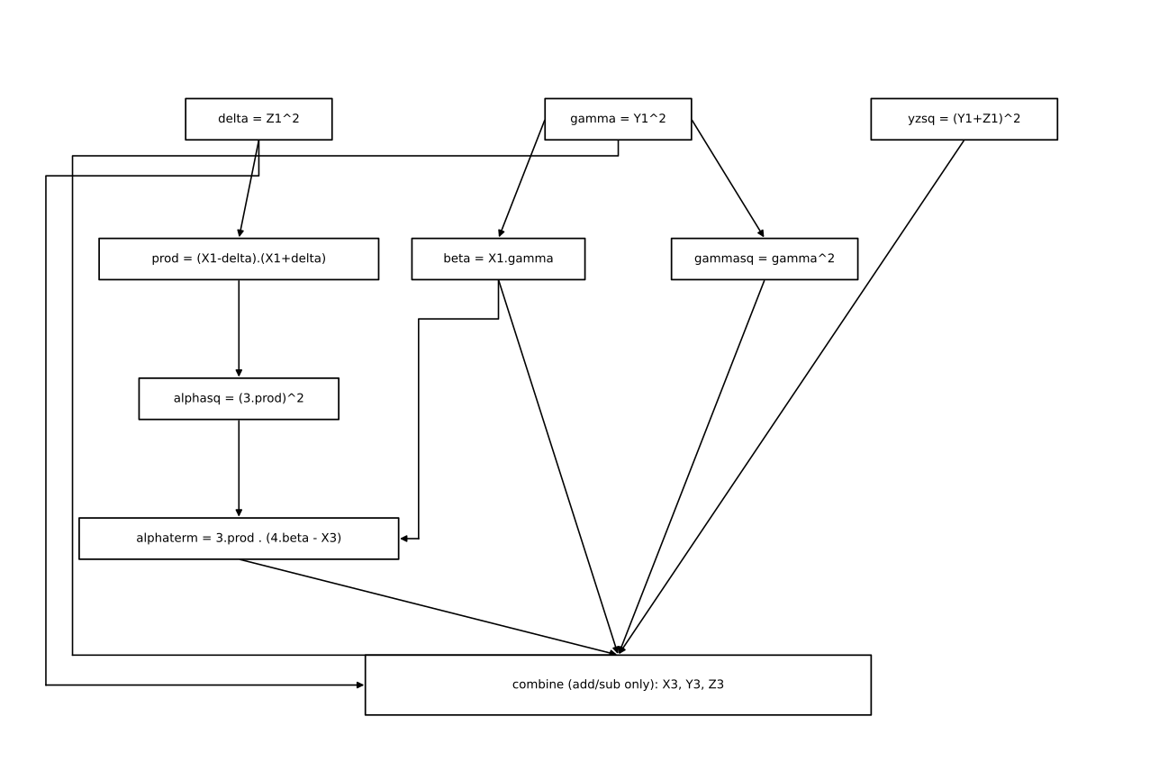
delta ← Z1^2
gamma ← Y1^2
beta  ← X1 . gamma
alpha ← 3 . (X1-delta) . (X1+delta)
X3 ← alpha^2 - 8.beta
Z3 ← (Y1+Z1)^2 - gamma - delta
Y3 ← alpha . (4.beta - X3) - 8.gamma^2
Eight of those steps are multiplications (including every square); the rest are additions and subtractions, free in this design.
ENTITY jac_point_double IS
    PORT (
        clk   : IN  STD_LOGIC;
        rst_n : IN  STD_LOGIC;
        start : IN  STD_LOGIC;
        x1_in, y1_in, z1_in : IN  UNSIGNED(W-1 DOWNTO 0);
        busy  : OUT STD_LOGIC;
        done  : OUT STD_LOGIC;
        x3_out, y3_out, z3_out : OUT UNSIGNED(W-1 DOWNTO 0)
    );
END ENTITY jac_point_double;
The architecture chains one shared multiplier through delta, gamma, beta, alpha's square, (Y1+Z1)'s square, alpha * term, and gamma's square in turn, using the same fp_mod_add/fp_mod_sub combinational helpers as the multiplier itself for every addition or subtraction along the way. x1_minus_delta, x1_plus_delta, beta2/beta4/beta8 (built by repeated doubling instead of a general multiply), and gamma2/gamma4/gamma8 are all instances of those two combinational entities, wired once and reused as each intermediate value becomes available.
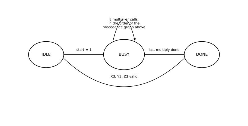
Cost. Eight multiplier calls, roughly 8 × 256 cycles.
Point addition
Add a fixed affine point
T1 ← Z2^2
T2 ← Z2 . T1
T3 ← X1 . T1
T4 ← Y1 . T2
T5 ← T3 - X2
T6 ← T4 - Y2
T7 ← T5^2
T8 ← T5 . T7
T9 ← X2 . T7
X3 ← T6^2 - T8 - 2.T9
Y3 ← T6.(T9 - X3) - Y2.T8
Z3 ← Z2 . T5
Eleven multiplications, three more than doubling: point addition has more field elements in play and less symmetry to exploit, the same trade-off seen in the binary-field design.
ENTITY jac_point_add IS
    PORT (
        clk   : IN  STD_LOGIC;
        rst_n : IN  STD_LOGIC;
        start : IN  STD_LOGIC;
        x1_in, y1_in : IN  UNSIGNED(W-1 DOWNTO 0);
        x2_in, y2_in, z2_in : IN  UNSIGNED(W-1 DOWNTO 0);
        busy  : OUT STD_LOGIC;
        done  : OUT STD_LOGIC;
        x3_out, y3_out, z3_out : OUT UNSIGNED(W-1 DOWNTO 0)
    );
END ENTITY jac_point_add;
No z1_in port, for the same reason as the binary-field design: the formula above requires
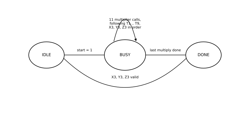
Cost. Eleven multiplier calls, roughly 11 × 256 cycles.
Two ways to walk the bits
Everything above is shared. From here, this design branches into two complete scalar multipliers built from the same field and point arithmetic: ecc_scalar_mult, which is fast on average, and ecc_scalar_mult_ct, which is the same speed on every run.
Variable time
ecc_scalar_mult walks the bits of
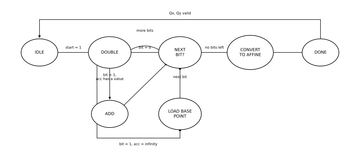
Cost. Up to 256 doublings and one addition for every set bit of
That word "typical" is the problem. This accelerator is meant to compute ecc_scalar_mult_ct exists.
Constant time: the Montgomery ladder
The fix, due to Montgomery [3], is to never let the sequence of operations depend on a bit's value. Keep two accumulators,
R0 ← infinity,  R1 ← P
for i from 255 downto 0:
    T ← R0 + R1                     # always
    D ← double(R_bit)               # always; R_bit means R1 if bit=1 else R0
    if bit i of k = 1:  R0 ← T,  R1 ← D
    else:                R0 ← D,  R1 ← T
return to_affine(R0)
Every round does exactly one addition and one doubling, in that order, no matter what the bit is. Only the register assignment afterward depends on the bit, and that assignment happens after both operations have already finished, so it costs no extra time to hide.
ENTITY ecc_scalar_mult_ct IS
    PORT (
        clk    : IN  STD_LOGIC;
        rst_n  : IN  STD_LOGIC;
        start  : IN  STD_LOGIC;
        k_in   : IN  UNSIGNED(W-1 DOWNTO 0);
        px_in  : IN  UNSIGNED(W-1 DOWNTO 0);
        py_in  : IN  UNSIGNED(W-1 DOWNTO 0);
        busy   : OUT STD_LOGIC;
        done   : OUT STD_LOGIC;
        result_is_infinity : OUT STD_LOGIC;
        qx_out : OUT UNSIGNED(W-1 DOWNTO 0);
        qy_out : OUT UNSIGNED(W-1 DOWNTO 0)
    );
END ENTITY ecc_scalar_mult_ct; dbl_in_x <= r1_x WHEN bit_val = '1' ELSE r0_x;
dbl_in_y <= r1_y WHEN bit_val = '1' ELSE r0_y;
dbl_in_z <= r1_z WHEN bit_val = '1' ELSE r0_z;
PA : ENTITY work.jac_point_add_general
PORT MAP (clk, rst_n, pa_start, r0_x, r0_y, r0_z, r1_x, r1_y, r1_z,
pa_busy, pa_done, pa_x3, pa_y3, pa_z3);
PD : ENTITY work.jac_point_double_par
PORT MAP (clk, rst_n, pd_start, dbl_in_x, dbl_in_y, dbl_in_z,
pd_busy, pd_done, pd_x3, pd_y3, pd_z3); WHEN ROUND_START =>
bit_val <= k_r(bit_idx);
pa_start <= '1';
pd_start <= '1';
pa_seen <= '0';
pd_seen <= '0';
state <= ROUND_WAIT;
WHEN ROUND_WAIT =>
IF pa_done = '1' THEN pa_seen <= '1'; END IF;
IF pd_done = '1' THEN pd_seen <= '1'; END IF;
IF (pa_seen = '1' OR pa_done = '1') AND (pd_seen = '1' OR pd_done = '1') THEN
state <= ROUND_LATCH;
END IF;
WHEN ROUND_LATCH =>
IF bit_val = '1' THEN
r0_x <= pa_x3; r0_y <= pa_y3; r0_z <= pa_z3;
r1_x <= pd_x3; r1_y <= pd_y3; r1_z <= pd_z3;
ELSE
r0_x <= pd_x3; r0_y <= pd_y3; r0_z <= pd_z3;
r1_x <= pa_x3; r1_y <= pa_y3; r1_z <= pa_z3;
END IF;
state <= NEXT_BIT;Both pa_start and pd_start rise on the same clock edge, whether the bit is 0 or 1. bit_val only decides which of r0/r1 feeds the doubler as dbl_in_*, and which result lands in r0 versus r1 afterward. Nothing here branches on bit_val before both operations have started; nothing skips either operation.
Notice which point modules this needs: jac_point_add_general, not the mixed jac_point_add. Neither jac_point_double_par, a doubler built from the same dbl-2001-b formula as before, but able to overlap independent multiplications across four multiplier instances instead of one, so that pairing it every round with the (inherently more expensive) general addition doesn't leave the doubler idle waiting.
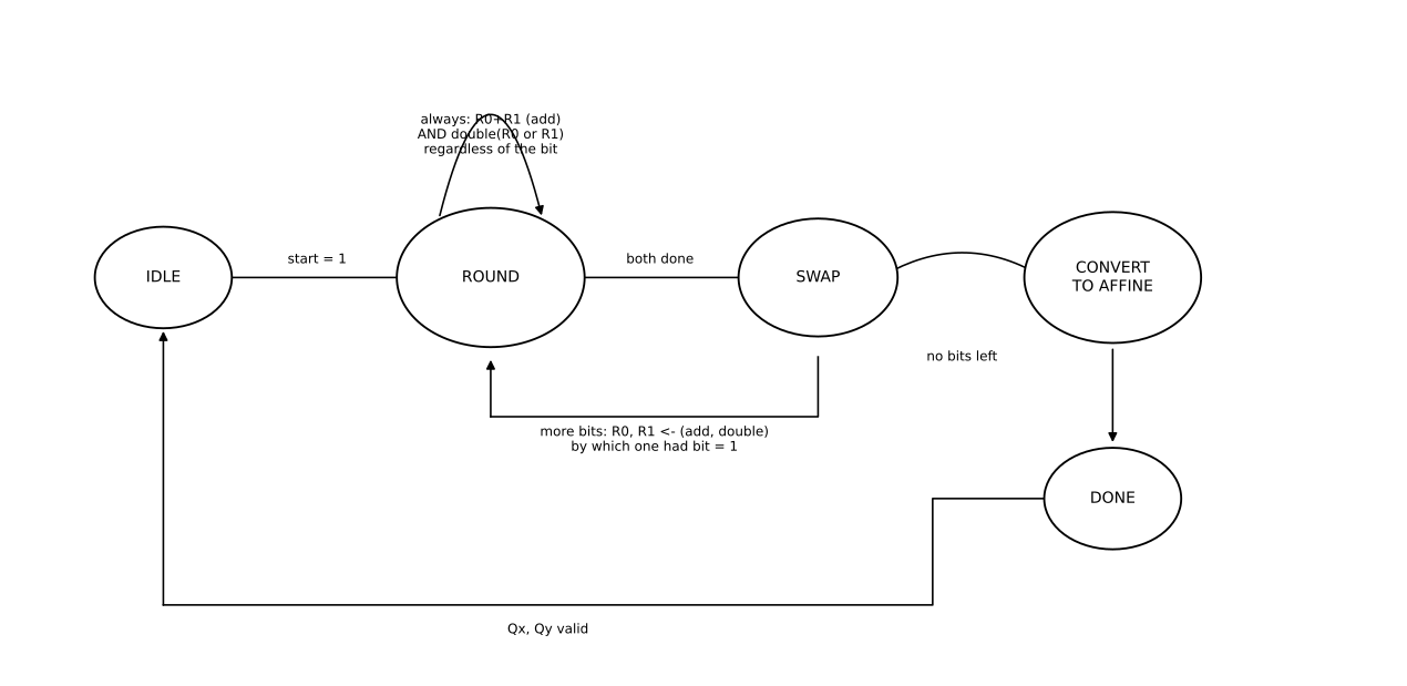
Cost. Exactly 256 rounds, no exceptions, each one bounded by the general addition's five multiplier rounds (the parallel doubling's four finish sooner and simply wait), plus the same inversion and two multiplications to close out. Whatever
General point addition and parallel doubling
The general addition formula, due to Bernstein and Lange [4], makes no assumption about either point's
Z1Z1 ← Z1^2                    U1 ← X1.Z2Z2        H ← U2 - U1
Z2Z2 ← Z2^2                    U2 ← X2.Z1Z1        I ← (2.H)^2
                                                     J ← H . I
S1 ← Y1.Z2.Z2Z2                r ← 2.(S2 - S1)
S2 ← Y2.Z1.Z1Z1                V ← U1 . I

X3 ← r^2 - J - 2.V
Y3 ← r.(V - X3) - 2.S1.J
Z3 ← ((Z1+Z2)^2 - Z1Z1 - Z2Z2) . H
Sixteen multiplications in total, twice as many as the mixed-coordinate version. What makes it worth using anyway is that many of them do not depend on each other. jac_point_add_general runs four multiplier instances side by side and schedules the sixteen products into five rounds:
| Round | Lane 0 | Lane 1 | Lane 2 | Lane 3 |
|---|---|---|---|---|
| 1 | Z1Z1 | Z2Z2 | (Z1+Z2)^2 | idle |
| 2 | U1 | U2 | Z2.Z2Z2 | Z1.Z1Z1 |
| 3 | S1 | S2 | I | Z3 |
| 4 | J | V | r^2 | idle |
| 5 | Y3 term 1 | Y3 term 2 | idle | idle |
    MULT0 : ENTITY work.fp_mult_interleaved PORT MAP (clk, rst_n, m_start, m0a, m0b, m_busy0, m_done0, m0p);
    MULT1 : ENTITY work.fp_mult_interleaved PORT MAP (clk, rst_n, m_start, m1a, m1b, m_busy1, m_done1, m1p);
    MULT2 : ENTITY work.fp_mult_interleaved PORT MAP (clk, rst_n, m_start, m2a, m2b, m_busy2, m_done2, m2p);
    MULT3 : ENTITY work.fp_mult_interleaved PORT MAP (clk, rst_n, m_start, m3a, m3b, m_busy3, m_done3, m3p);
Five rounds of 256 cycles each beats eleven rounds outright, even though sixteen multiplications is more total work than the mixed formula's eleven. Parallel hardware, not less arithmetic, buys the speed here.
jac_point_double_par runs the same dbl-2001-b formula as the sequential doubler, across the same four lanes, in four rounds instead of eight:
| Round | Lane 0 | Lane 1 | Lane 2 | Lane 3 |
|---|---|---|---|---|
| 1 | delta | gamma | idle | idle |
| 2 | beta | prod (-> alpha) | gammasq | yzsq |
| 3 | alphasq | idle | idle | idle |
| 4 | alpha . term | idle | idle | idle |
Both modules also handle the point at infinity explicitly. jac_point_add_general checks
Converting back to affine
The relation is the same one from the coordinates section:
zinv  ← invert(Z)
zinv2 ← zinv^2
zinv3 ← zinv2 . zinv
x ← X . zinv2
y ← Y . zinv3
One inversion, three more multiplications (one to build
Reaching real hardware: AXI-Lite
Where the binary-field design used UART, this one exposes a memory-mapped AXI-Lite slave, the standard on-chip bus for connecting a hardware block to a processor (an ARM core on a Zynq SoC, for this design). A host writes
| Address | Register |
|---|---|
0x00 | control: write bit 0 to start |
0x04 | status: bit 0 busy, bit 1 done, bit 2 result is infinity |
0x10–0x2C | k, eight 32-bit words, big-endian |
0x30–0x4C | |
0x50–0x6C | |
0x70–0x8C | |
0x90–0xAC |
    CORE : ENTITY work.ecc_scalar_mult_ct
        PORT MAP (
            clk => s_axi_aclk, rst_n => s_axi_aresetn,
            start => core_start, k_in => k_in_r, px_in => px_in_r, py_in => py_in_r,
            busy => core_busy, done => core_done,
            result_is_infinity => core_result_is_infinity,
            qx_out => core_qx, qy_out => core_qy
        );
The wrapper always instantiates the constant-time core, not the variable-time one: whatever calls into this accelerator over the bus gets the side-channel-resistant version by default.
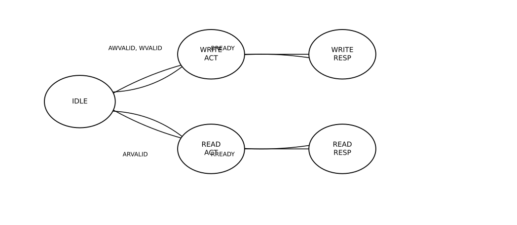
Cost. One AXI write burst to load three 256-bit operands (eight 32-bit writes each), one scalar multiplication, and however many status reads the host chooses to poll with.
Cost summary
| Operation | Multiplier calls | Cycles (approx.) | Notes |
|---|---|---|---|
| Modular add / sub | 0 | 0 | combinational |
| Multiplication | 1 | 256 | double-and-add, MSB first |
| Inversion | 384 | ≈ 384 × 256 | square-and-multiply, no free squaring |
| Point doubling (sequential) | 8 | ≈ 8 × 256 | dbl-2001-b [1] |
| Point addition (mixed) | 11 | ≈ 11 × 256 | madd-2004-hmv [2], requires |
| Point doubling (parallel) | 8 | ≈ 4 × 256 | same formula, 4 lanes |
| Point addition (general) | 16 | ≈ 5 × 256 | add-2007-bl [4], 4 lanes |
| Scalar mult., variable time | data-dependent | ≈ 984,000 typical | ≈256 doublings, ≈128 additions |
| Scalar mult., constant time | fixed | ≈ 426,000 always | 256 rounds of 1 add + 1 double |
The two scalar-multiplication rows are counted the same way as everything above them: from the state machines, not from a board measurement. The constant-time figure is exact, by construction, for every
References
[1] D.J. Bernstein, "A software implementation of NIST P-224," 2001. Formula "dbl-2001-b" in the Explicit-Formulas Database [5].
[2] D. Hankerson, A. Menezes, S. Vanstone, Guide to Elliptic Curve Cryptography, Springer, 2004, p. 91.
[3] P.L. Montgomery, "Speeding the Pollard and elliptic curve methods of factorization," Mathematics of Computation, 48(177), 1987, pp. 243–264.
[4] D.J. Bernstein and T. Lange, "Faster addition and doubling on elliptic curves," in Advances in Cryptology, ASIACRYPT 2007, LNCS 4833, Springer, 2007, pp. 29–50.
[5] D.J. Bernstein and T. Lange, Explicit-Formulas Database (EFD), https://www.hyperelliptic.org/EFD/.
[6] Standards for Efficient Cryptography Group, SEC 2: Recommended Elliptic Curve Domain Parameters, Version 1.0, 2000. (secp256r1 / NIST P-256)
[7] National Institute of Standards and Technology, FIPS PUB 186-4: Digital Signature Standard (DSS), 2013. Appendix D.